- 您现在的位置:买卖IC网 > Sheet目录1014 > Y92B-A250 (Omron Electronics Inc-IA Div)HEATSINK SSR FOR G3NA SERIES
�� �
�
�Operating and Storage Locations�
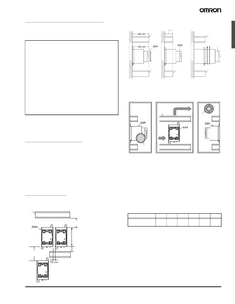
�Relationship� between� SSRs� and� Duct� Height�
�Do� not� use� or� store� the� G3NA� in� the� following� locations.� Doing� so�
�may� result� in� damage,� malfunction,� or� deterioration� of� performance�
�characteristics.�
�Incorrect� Example�
�D� u� ct�
�Countermeasure� 1�
�50� mm� max.�
�(A� height� of� no�
�more� than� half�
�Countermeasure� 2�
�D� u� ct�
�the� SSR's� height�
�?� Do� not� use� or� store� in� locations� subject� to� direct� sunlight.�
�?� Do� not� use� in� locations� subject� to� ambient� temperatures� outside�
�the� range� –20� to� 60� °� C.�
�?� Do� not� use� in� locations� subject� to� relative� humidity� outside� the�
�range� 45%� to� 85%� or� locations� subject� to� condensation� as� the�
�V� ertical�
�direction�
�is� recommended.)�
�Base�
�Airflo� w�
�SSR�
�result� of� severe� changes� in� temperature.�
�?� Do� not� store� in� locations� subject� to� ambient� temperatures� outside�
�the� range� –30� to� 70� °� C.�
�D� u� ct�
�D� u� ct�
�D� u� ct�
�?� Do� not� use� or� store� in� locations� subject� to� corrosive� or� flammable�
�gases.�
�?� Do� not� use� or� store� in� locations� subject� to� dust� (especially� iron�
�dust)� or� salts.�
�?� Do� not� use� or� store� in� locations� subject� to� shock� or� vibration.�
�Do� not� s� u� rro� u� nd� the� SSR�
�w� ith� d� u� cts,� other� w� ise� the�
�heat� radiation� of� the� SSR�
�w� ill� b� e� ad� v� ersely� affected.�
�Use� short� d� u� cts.�
�If� the� d� u� cts� cannot� b� e�
�shortened,� place� the� SSR� on�
�a� metal� b� ase� so� that� it� is� not�
�s� u� rro� u� nded� b� y� the� d� u� cts.�
�?� Do� not� use� or� store� in� locations� subject� to� exposure� to� water,� oil,� or�
�chemicals.�
�?� Do� not� use� or� store� in� locations� subject� to� high� temperatures� or�
�high� humidity.�
�?� Do� not� use� or� store� in� locations� subject� to� salt� damage.�
�?� Do� not� use� or� store� in� locations� subject� to� rain� or� water� drops.�
�■� Precautions� for� Correct� Use�
�Please� observe� the� following� precautions� to� prevent� failure� to� oper-�
�ate,� malfunction,� or� undesirable� effect� on� product� performance.�
�Before Actual Operation�
�1.� The� G3NA� in� operation� may� cause� an� unexpected� accident.�
�Therefore� it� is� necessary� to� test� the� G3NA� under� the� variety� of�
�conditions� that� are� possible.� As� for� the� characteristics� of� the�
�G3NA,� it� is� necessary� to� consider� differences� in� characteristics�
�between� individual� SSRs.�
�2.� Unless� otherwise� specified,� the� ratings� in� this� catalog� are� tested�
�values� in� a� temperature� range� between� 15� °� C� and� 30� °� C,� a� relative�
�humidity� range� between� 25%� and� 85%,� and� an� atmospheric� pres-�
�sure� range� between� 88� and� 106� kPa� (standard� test� conditions�
�according� to� JIS� C5442).� It� will� be� necessary� to� provide� the� above�
�conditions� as� well� as� the� load� conditions� if� the� user� wants� to� con-�
�firm� the� ratings� of� specific� G3NAs.�
�Mounting Method�
�SSR� Mounting� Pitch� (Panel� Mounting)�
�D� u� ct�
�Ventilation� Outside� the� Control� Panel�
�Be� a� w� are� of� airflo� w�
�D� u� ct�
�Ventilation�
�o� u� tlet�
�(axial� fan)�
�Air� inlet�
�If� the� air� inlet� or� air� outlet� has� a� filter,� clean� the� filter� regularly� to� pre-�
�vent� it� from� clogging� to� ensure� an� efficient� flow� of� air.�
�Do� not� locate� any� objects� around� the� air� inlet� or� air� outlet,� otherwise�
�the� objects� may� obstruct� the� proper� ventilation� of� the� control� panel.�
�A� heat� exchanger,� if� used,� should� be� located� in� front� of� the� SSRs� to�
�ensure� the� efficiency� of� the� heat� exchanger.�
�?� Please� reduce� the� ambient� temperature� of� SSRs.� The� rated� load�
�current� of� an� SSR� is� measured� at� an� ambient� temperature� of� 40� °� C.�
�?� An� SSR� uses� a� semiconductor� in� the� output� element.� This� causes�
�the� temperature� inside� the� control� panel� to� increase� due� to� heating�
�resulting� from� the� passage� of� electrical� current� through� the� load.� To�
�restrict� heating,� attach� a� fan� to� the� ventilation� outlet� or� air� inlet� of�
�the� control� panel� to� ventilate� the� panel.� This� will� reduce� the� ambient�
�temperature� of� the� SSRs� and� thus� increase� reliability.� (Generally,�
�each� 10� °� C� reduction� in� temperature� will� double� the� expected� life.)�
�Load� current� (A)�
�5A�
�10� A�
�20� A�
�40� A�
�75� A�
�90� A�
�60� mm� min.�
�Required� number�
�of� fans� per� SSR�
�0.08�
�0.16�
�0.31�
�0.62�
�1.2�
�1.44�
�Example:� For� 10� SSRs� with� load� currents� of� 10� A,�
�0.16� x� 10� =� 1.6�
�Vertical� direction�
�Thus,� 2� fans� would� be� required.�
�80� mm� min.�
�30� mm� min.�
�Size� of� fans:� 92� mm� 2� ,� Air� volume:� 0.7� m� 3� /min,�
�Ambient� temperature� of� control� panel:� 30� °� C�
�If� there� are� other� instruments� that� generate� heat� in� the� control� panel�
�other� than� SSRs,� additional� ventilation� will� be� required.�
�Solid� State� Relay�
�G3NA�
�481�
�发布紧急采购,3分钟左右您将得到回复。
相关PDF资料
ZXSC310EV
BOARD EVALUATION FOR ZXSC310E5TA
000-16300
CONN PLUG BNC RG-180B/U
000-36800
CONN JACK BNC STR CRIMP RG58,141
000-53175
CONN PLUG 7/8 TRIAX 21-529 CABLE
000-79875
CONN PLUG TNC CLAMP STR 58/U
000-86350
CONN JACK BNC BULKHD RG174 188
0001.1001.TR
FUSE 500MA 250V 5X20 FAST CERM
0001.1006
FUSE 1.6A 250V 5X20 FAST CERM
相关代理商/技术参数
Y92BN100
制造商:OMRON AUTOMATION AND SAFETY 功能描述:HEAT SINK TRACK MNT FOR G3NA SER 制造商:OMRON INDUSTRIAL AUTOMATION 功能描述:Solid State Relay, Heat Sinks
Y92B-N100
功能描述:散热片 TRK MT HEAT SINK G3N RoHS:否 制造商:Ampro By ADLINK 产品:Heat Sink Accessories 安装风格:Through Hole 散热片材料: 散热片样式: 热阻: 长度: 宽度: 高度: 设计目的:Express-HRR
Y92BN150
制造商:OMRON AUTOMATION AND SAFETY 功能描述:HEAT SINK TRACK MNT FOR G3NA SER 制造商:Omron Electronic Components LLC 功能描述:Heat Sink Passive Screw 1.38|C/W 制造商:OMRON INDUSTRIAL AUTOMATION 功能描述:Heat Sink Passive Screw 1.38°C/W
Y92B-N150
功能描述:散热片 TRK MT HEAT SINK G3N RoHS:否 制造商:Ampro By ADLINK 产品:Heat Sink Accessories 安装风格:Through Hole 散热片材料: 散热片样式: 热阻: 长度: 宽度: 高度: 设计目的:Express-HRR
Y92BN50
制造商:OMRON AUTOMATION AND SAFETY 功能描述:HEAT SINK TRACK MNT FOR G3NA SER 制造商:OMRON INDUSTRIAL AUTOMATION 功能描述:Solid State Relay, Heat Sinks
Y92B-N50
功能描述:散热片 TRK MT HEAT SINK G3N RoHS:否 制造商:Ampro By ADLINK 产品:Heat Sink Accessories 安装风格:Through Hole 散热片材料: 散热片样式: 热阻: 长度: 宽度: 高度: 设计目的:Express-HRR
Y92BN50V
制造商:Omron Corporation 功能描述:
Y92BP100
制造商:OMRON AUTOMATION AND SAFETY 功能描述:HEAT SINK 1.01C/W 450G FOR G3PB 制造商:OMRON INDUSTRIAL AUTOMATION 功能描述:Heat Sink Passive 1.01°C/W